#A Rubik’s microfluidic cube
“#A Rubik’s microfluidic cube”
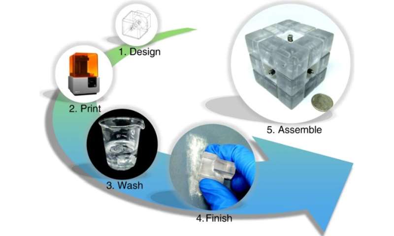
Scientists have recently engineered a modular system based on the Rubik’s cube to design and reconfigure microfluidic systems. Research teams had previously pursued the arrangement of microfluidic blocks in diverse conformations to suit varied experiments. In this work, Xiaochen Lai and a team of scientists at the Tianjin University in China were inspired by the popular Rubik’s puzzle to build a three-dimensional (3-D) microfluidic system. The setup could be easily twisted and turned to change its function. They mimicked the design of the Rubik’s cube with modular pieces containing microchannel layouts to achieve a tight, leak-proof seal relative to device arrangement. Lai et al. used a single device to perform fluid mixing and droplet-based microbial culture for a range of practical applications as microfluidic sensors, pumps and valves in resource-limited settings. The work is now published on Nature: Microsystems and Microengineering.
Microfluidic systems are highly useful in scientific research for a range of activities including chemical analysis due to their reaction speed and high throughput functionality. However, the technology is still in development and its potential remains to be fully explored since the process of microfluidic fabrication is still expensive and time consuming. To rapidly deploy customized microfluidic systems, bioengineers have proposed the concept of modular microfluidics, in which individual microfluidic blocks can be engineered in a modular design and assembled to form a system. In the present study, Lai et al. proposed a reconfigurable microfluidic system adapted from the Rubik’s cube due to several unique features of the construct. To begin with, the Rubik’s cube contained an ingenious interlocking mechanism to prevent leakage during easy reconfiguration. Second, the transformation from one state to another only required a maximum of 20 twists of the cube to ensure ease of use. Furthermore, the cube could be scrambled to a variety of states from the starting position for diverse microfluidic configurations. The proposed system provides an easy and affordable process that paves way toward highly customized applications in resource-limited settings.
Designing and characterizing the microfluidics cube
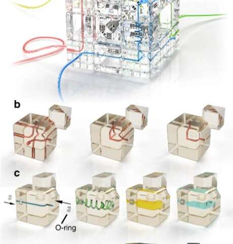
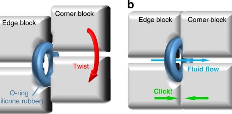
The system appeared as an ordinary Rubik’s cube, but all 12 edge cubes and eight corner cubes were placed with blocks containing internal microchannels to perform microfluidic functions. Each of the edge and corner blocks maintained an independent microfluidic chip, where its inlet/outlet was located at the geometrical center of a surface. Lai et al. 3-D printed all these blocks using a desktop stereolithography (SLA) printer. They used clear resin to obtain transparency for ease of observation and included two silicone rubber O-rings into each edge block to ensure an integrated system with smooth rotation. The O-ring-aided sealing strategy ensured sealed contact between the blocks for their automated alignment.
After developing the microfluidic cube blocks, the team evaluated their performance by determining their dimension and tolerance. They noted fabrication errors during 3-D printing, although such errors did not cause fluid leakage during its activity due to the O-ring aided sealing strategy. They then tested the pressure resistance of the microfluidics system, which depended on the tightness of the spring to keep the blocks together with leakproof fluid flow. The high pressure resistance in the cube also resulted due to its structure. To accomplish high quality imaging between the channel and the cube, Lai et al. aimed to custom-build blocks with biased channels and chambers near the cube surface for self-sufficient observations of the microchannels.
Reconfiguring the microfluidics cube –
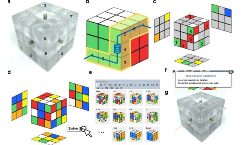
The scientists reconfigured the microfluidics by turning the faces of the cube and detected the sequence by following Rubik’s algorithms—a set of memorized moves with a specific effect on the cube. Usually, a sequence of movements of an algorithm is referred to as Singmaster rotation where capital letters represent each move. Each transformation was possible within seconds, and at some instances, Lai et al. used simpler algorithms for faster transformation. Using algorithms the team designated the position of most of the blocks in the cube to customize the microfluidics, but there were some intrinsic limits to the Rubik’s cube relative to the microfluidics arrangement, which they reconfigured with the help of an online Rubik’s cube solver. The scientists set the final arrangement of microfluidics blocks to the unscrambled state and calculated an algorithm for configuration as a relatively optimized solution to the Rubik’s cube. Since the proven maximum number of moves required to restore any of the permutations of a Rubik’s cube, also known as the God’s number, is 20, the same rules applied to the present system. Therefore, if Lai et al. were to reconfigure a specific microfluidic system from a completely unarranged state, 20 moves were sufficient.
Applications of the microfluidic cube –
The proposed setup has several advantages compared to previously reported modular microfluidics, including leak-proof ease of use and disassembly free reconfiguration in resource-limited settings. To demonstrate its usefulness, the scientists completed a series of scenarios. They formed a T-junction block for homogenous liquid mixing and then reconfigured the microfluidic cube to create a droplet generator. The new setup allowed water-in-oil droplets generation for their collection, observation and further functionality. Such microfluidic devices allow a large amount of parallel reactions to occur for high throughput applications. For real-world applications, Lai et al. conducted droplet-based microbial culturing experiments with the proposed microfluidic cube. Microbial culturing is essential for a range of diagnostics, genetics and bioengineering applications for highly parallel and high throughput research on bacterial evolution. In this experiment, the scientists used Escherichia coli culture, incubated the microfluidic cube at room temperature and used resazurin as a cell viability indicator to evaluate the cells during culture. The team monitored cell activity based on the color change of the droplets that turned from blue to pink at first, and then faded, to prove bacterial activity in the droplets. The scientists also estimated the concentration of bacterial populations during the experiment.
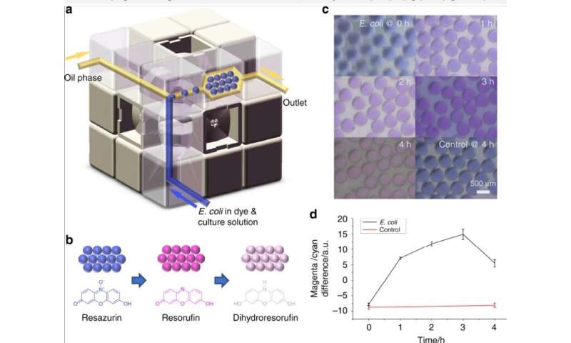
In this way, Xiaochen Lai and team presented a new method to rapidly build custom microfluidic systems by playing a microfluidic Rubik’s cube. The setup allowed flexible assembly of diverse microfluidic blocks by simply rotating the faces of the cube. After each rotation, the team self-aligned and sealed all blocks for versatile microfluidic functions under the guidance of a simple Rubik’s cube algorithm. As a proof of concept, they created a 3-D printed block to form cube-shaped microfluidic systems for good reconfigurability and rapid onsite deployment. The scientists aim to improve the versatility of the microfluidics cubes for advanced applications. The present setup will facilitate custom microfluidic systems in resource-limited settings.
More information:
Xiaochen Lai et al. A Rubik’s microfluidic cube, Microsystems & Nanoengineering (2020). DOI: 10.1038/s41378-020-0136-4
Krisna C. Bhargava et al. Discrete elements for 3-D microfluidics, Proceedings of the National Academy of Sciences (2014). DOI: 10.1073/pnas.1414764111
George M. Whitesides. The origins and the future of microfluidics, Nature (2006). DOI: 10.1038/nature05058
© 2020 Science X Network
A Rubik’s microfluidic cube (2020, June 26)
retrieved 26 June 2020
from https://phys.org/news/2020-06-rubik-microfluidic-cube.html
This document is subject to copyright. Apart from any fair dealing for the purpose of private study or research, no
part may be reproduced without the written permission. The content is provided for information purposes only.
If you want to read more Like this articles, you can visit our Science category.
if you want to watch Movies or Tv Shows go to Dizi.BuradaBiliyorum.Com for forums sites go to Forum.BuradaBiliyorum.Com


